
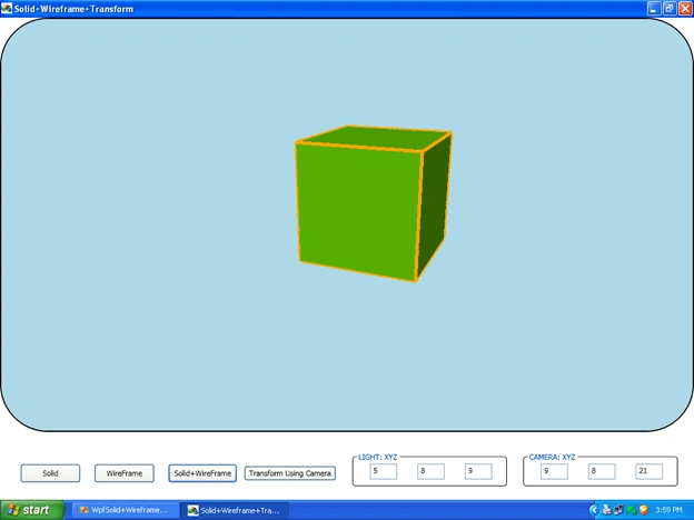
In the very beginning I decided to make a project that (1) renders 3D objects (2) Wireframe object and (3) does basic operations for 3D objects. And this article is the result of this process.
One thing that shocked me was that WPF does not render wireframe objects but thank God that the 3DTool provides the ScreenSpaceLine3D class that allows us to render wireframe objects.
Requirements
- VS 2008 or onwards version.
- 3DTool DLL.
- Basic Mathematical and WPF knowledge.
INDEX
- Read Important Definitions
- Set Camera and Light
- Draw solid cube
- Draw Wireframe cube
- Transform above cube's that is Solid and Wire frame cube.
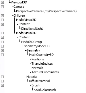
The following image shows the hierarchy which we have to follow to render 3D object.
- VIEWPORT3D:
- CAMERA:
- MODELVISUAL3D:
- LIGHT:
- MODEL3DGROUP:
- GeometryModel3D:
Two very basic properties of this class will help us in creating 3D objects. And both properties are as below. You can also see the hierarchy in the preceding image
1. Geometry
MeshGeometry3D:
Geometry property of GeometryModel3D class contains the instance of the MeshGeometry3D class.
MeshGeometry3D is used to create a mesh.
Now what is the mesh and what is the use of it?
You can compare the mesh with the skeleton of our body.
Mesh is skeleton of 3D models.
It is used to create the surface of the 3D models.
And to create a surface it uses a very basic geometry shape and as we all know it is a TRIANGLE.
So MESH will use TRIANGLE as the basic building blocks to represent Surface.
The Reason for using a TRIANGLE is that it can represent more information than any other geometrical shape such as square, pentagon, hexagon or any polygon.
Mesh is consisting of Points and Lines.
Points represent the positions in 3d world space and line connects those positions to establish the surface area. The MeshGeometry3D class contains three very basic properties that are frequently used in creating 3D objects and these are as below
1. Position
Position represents the location of a single point in 3D world space.
2. TriangleIndices
The mesh position only describes the three points of the triangle (very basic shape to create mesh) in mesh.
In order to create the mesh, after adding the position we need to define the points of the triangles and that can be done through TriangleIndices.
In WPF, the order in which you add triangle indices is very important.
Because it affects the visibility of triangle represent by triangleindices.
Let's say,
Suppose, we are looking at the triangular surface.
If we define the triangle's indices in a clock-wise direction then the side we are looking at will be invisible or we can say that what we see are the back side of that triangular surface.
If we define triangle indices in a counter-clockwise direction, then the side we are looking at will be visible or what we are seeing is the front face of that triangular surface.
NOTE: in the above case though you give the triangle indices in a clock-wise direction so you can see the surface if you have provided background material.
3. NORMAL:
Mathematically, a vector is normally perpendicular to the surface.
See the image below.
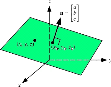
In order to get the best edge discrimination of a 3D-Object we have to add Normals for each position in the mesh.
Triangleindices decides visibility and invisibility (Front or Back side of Triangle)
Whereas Normals are used by the light sources to decide how much light will take each triangle (in mesh).
2. Material
Material represents the texture of the 3D Geometries. Combined with a light source.
There are four basic materials used in WPF as below.
Diffuse,Specular,emissive,Combined
For more detailed explanation on material go here
2. Set Camera and Light
To set camera and light see the code below and image I think I don't need to write any thing for explaining definitions.
You can also see the same code in demo projects .xaml file
Code <PerspectiveCamera x:Name="camera" FarPlaneDistance="100" LookDirection="-9,-8,-21" UpDirection="0,1,0" NearPlaneDistance="1" Position="9,8,21" FieldOfView="70" /> </Viewport3D.Camera> <ModelVisual3D> <ModelVisual3D.Content> <DirectionalLight x:Name="directionLightOfMainViewPort" Color="White" Direction="-5,-8,-9" /> </ModelVisual3D.Content> </ModelVisual3D> </Viewport3D> |
Code |
3. Draw Solid Cube
In order to draw solid cube follow the steps below.
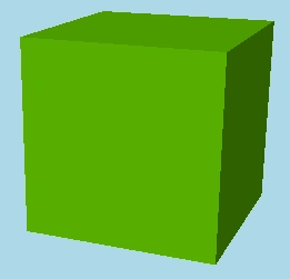
EXPLANATION:
I will explain from bottom to top, which means from GeometryModel3D to Viewport3D
FIRST: At very first create MeshGeometry3D(meshGeo) with its three basic properties.
After creating the mesh (meshGeo), add MeshGeometry3D(meshGeo) and Material(material) in the GeometryModel3D(geoModel).
Code
MeshGeometry3D meshGeo;
Material material;
//Create MESH
meshGeo = new MeshGeometry3D();
// Add Position in MESH
meshGeo.Positions.Add(p0);
meshGeo.Positions.Add(p1);
meshGeo.Positions.Add(p2);
// Add triangleIndices in MESH
meshGeo.TriangleIndices.Add(0);
meshGeo.TriangleIndices.Add(1);
meshGeo.TriangleIndices.Add(2);
// Add normal in MESH
Vector3D normal = CalculateNormal(p0, p1, p2);
meshGeo.Normals.Add(normal);
meshGeo.Normals.Add(normal);
meshGeo.Normals.Add(normal);
// Create MATERIAL
material = new DiffuseMaterial(new SolidColorBrush(Colors.LawnGreen));
// Create GEOMETRYMODEL3D wich tackes MESH adn MATERIAL as arguments
geoModel = new GeometryModel3D(meshGeo, material);
|
See the image below.
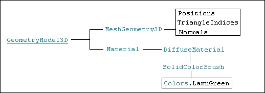
SECOND: Add GeometryModel3D(geoModel) in Model3DGroup(modelGroup)
See the below code.
... //Add GEOMETRYMODEL3D in MODEL3DGROUP
Model3DGroup modelGroup;
//Create MODEL3DGROUP
modelGroup = new Model3DGroup();
modelGroup.Children.Add(geoModel);
See the image below.

THIRD: Add collection of Model3DGroup(cubeM3DGroup) in ModelVisual3D(solidCubeMV3D).
See the code below.
//Add MODEL3DGROUP in MODELVISUAL3D // Store the instance of Transform3DGroup class in Transform Property of "solidCubeMV3D"
solidCubeMV3D = new ModelVisual3D();
Model3DGroup cubeM3DGroup = new Model3DGroup();
//front side triangles
cubeM3DGroup.Children.Add(CreateTriangleFacet(p3, p2, p6));
cubeM3DGroup.Children.Add(CreateTriangleFacet(p3, p6, p7));
//right side triangles
cubeM3DGroup.Children.Add(CreateTriangleFacet(p2, p1, p5));
cubeM3DGroup.Children.Add(CreateTriangleFacet(p2, p5, p6));
//back side triangles
cubeM3DGroup.Children.Add(CreateTriangleFacet(p1, p0, p4));
cubeM3DGroup.Children.Add(CreateTriangleFacet(p1, p4, p5));
//left side triangles
cubeM3DGroup.Children.Add(CreateTriangleFacet(p0, p3, p7));
cubeM3DGroup.Children.Add(CreateTriangleFacet(p0, p7, p4));
//top side triangles
cubeM3DGroup.Children.Add(CreateTriangleFacet(p7, p6, p5));
cubeM3DGroup.Children.Add(CreateTriangleFacet(p7, p5, p4));
//bottom side triangles
cubeM3DGroup.Children.Add(CreateTriangleFacet(p2, p3, p0));
cubeM3DGroup.Children.Add(CreateTriangleFacet(p2, p0, p1));
solidCubeMV3D.Content = cubeM3DGroup;
// it will later use to rotate the object
solidCubeMV3D.Transform = new Transform3DGroup();
NOTE: Assign transform property of (solidCubeMV3D) to later use in rotation of object.
See the below image.

FOURTH: Add ModelVisual3D(solidCubeMV3D) in the Viewport3D(mainViewPort)
See the code below.
//Add MODELVISUAL3D in VIEWPORT3D
See the image below.

4. Draw Wireframe Cube
In order to draw wireframe object you need 3DTool.dll.
I have added it in my DemoProject "3DTOOL DLL" folder.
So, just add reference to that .dll if you don't have.
To add reference of 3DTool in your project Following the steps:
1.Go to the Solution Explorer
2.Right Click on References
3.Select: Add References… will open new dialogue box
4.Click on Browse
5.Navigate to 3DTool.dll
6.Click on OK. That's it
Now, how to draw wireframe cube. 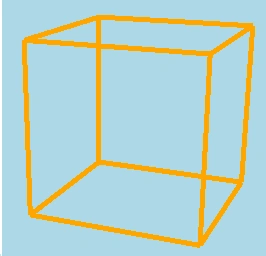
FIRST: Create the instance of ScreenSpaceLines3D(wireFrameCube) and set it's three properties and that is "Thickness", "Color", "Points".
And also set the "Transform" property to later use in Rotation of "wireFrameCube".
See the code below.
Color c = Colors.Orange; wireFrameCube.Thickness = width; wireFrameCube.Points.Add(p0); wireFrameCube.Points.Add(p1); wireFrameCube.Points.Add(p2); wireFrameCube.Points.Add(p3); wireFrameCube.Points.Add(p4); wireFrameCube.Points.Add(p5); wireFrameCube.Points.Add(p6); wireFrameCube.Points.Add(p7); wireFrameCube.Points.Add(p0); wireFrameCube.Points.Add(p1); wireFrameCube.Points.Add(p2);
wireFrameCube = new ScreenSpaceLines3D();
int width = 5;
wireFrameCube.Color = c;
wireFrameCube.Points.Add(p1);
wireFrameCube.Points.Add(p2);
wireFrameCube.Points.Add(p3);
wireFrameCube.Points.Add(p0);
wireFrameCube.Points.Add(p5);
wireFrameCube.Points.Add(p6);
wireFrameCube.Points.Add(p7);
wireFrameCube.Points.Add(p4);
wireFrameCube.Points.Add(p4);
wireFrameCube.Points.Add(p5);
wireFrameCube.Points.Add(p6);
wireFrameCube.Points.Add(p3);
wireFrameCube.Points.Add(p7);
wireFrameCube.Transform = new Transform3DGroup();
See the image below.

SECOND: Simply and directly add the ScreenSpaceLines3D(wireFrameCube) to the Viewport3D(mainViewPort).
See the code below.
this.mainViewPort.Children.Add(wireFrameCube);
That's it you have created wireframe cube.
See the image below.

NOTE: Suppose a line is being drawn using four points then two intermediate points will be used two times or we add intermediate points twice.
See the below image to clsrify the idea.
wireFrameCube.Thickness = width; wireFrameCube.Points.Add(P1); wireFrameCube.Points.Add(P2); wireFrameCube.Points.Add(P3);
Code to draw this line in viewport is as below.
NOTE: after using the code below you just see straight line in ViewPort3D.
You will not see Red points and labels of points.
ScreenSpaceLines3D wireFrameCube = new ScreenSpaceLines3D();
ScreenSpaceLines3D wireFrameCube = new ScreenSpaceLines3D();
Color c = Colors.Orange;
int width = 5;
wireFrameCube.Color = c;
wireFrameCube.Points.Add(P2);
wireFrameCube.Points.Add(P3);
wireFrameCube.Points.Add(P4);
this.mainViewPort.Children.Add(wireFrameCube);
You can see that points P3 and P4 are used twise. To represent straight line.
5.TRANSFORM
To transform objects in Viewport3D we have two options.
5.1. Transformation of object or
5.2. Transformation of camera.
To make it clear let's take one example.
Suppose,
a. One cube is in your hand and you are rotating it with your fingers.
Then that is the first one---> [Transformation of object]
b. One cube is on table and you are rotating around the cube or table,
Then that this is the second one ---> [Transformation of camera]
Here, you can compare yourself as a camera.
5.1 Transformation of object
In order to transform an object you have to decide two things
1.Rotation Axis and
2.Angle to rotate around specified axis.
We can decide Rotation Axis and angle using the mouse movement and some calculations.
See the image below...
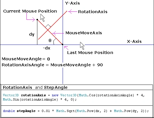
RotationAxis:
In ordert to calculate rotationAxis we will first calculate mouseMoveAngle after adding 90 degree in it; that will give us rotationAxisAngle and then as shown in the image below using some basic mathematics we can find rotationAxis.
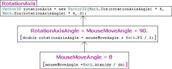
Angle of Rotation or StepAngle:
You can give any constant value to Angle of Rotation (stepAngle).
Or you can also use the following formula.
double stepAngle = 0.01 * Math.Sqrt(Math.Pow(dx, 2) + Math.Pow(dy, 2));
Now, we have Axis and Angle so we can now rotate the object using any one of Code Block below.
A. Transform using QuaternionRotation3D:
QuaternionRotation3D qr = new QuaternionRotation3D(new Quaternion(axisArg, stepAngleArg* 180 Math.PI));
RotateTransform3D r = new RotateTransform3D(qr);
group.Children.Add(r);
Transform3DGroup group = solidCubeMV3D.Transform as Transform3DGroup;
B. Transform Using AxisAngleRotation3D:
AxisAngleRotation3D a = new AxisAngleRotation3D(); RotateTransform3D r1 = new RotateTransform3D(a);
group.Children.Add(r1);
Transform3DGroup group = solidCubeMV3D.Transform as Transform3DGroup;
a.Axis = axisArg;
a.Angle = stepAngleArg *(180 / Math.PI);
5.2 Transformation of camera. #region - QuaternionRotation3D - #region - AxisAngleRotation3D - camera.Position = rotationTransform.Transform(camera.Position);
We can transform objects using camera's position and up direction also.
I have put one button in my demo project for transforming an object using camera.
And as above you can use QuaternionRotation3D or AxisAngleRotation3D.
Vector3D rotationAxis = Vector3D.CrossProduct((Vector3D)camera.Position, camera.UpDirection);
//RotateTransform3D rotationTransform = new RotateTransform3D(new QuaternionRotation3D(new Quaternion(rotationAxis, 1.0)));
#endregion
RotateTransform3D rotationTransform = new RotateTransform3D(new AxisAngleRotation3D(rotationAxis, 1.0));
#endregion
camera.UpDirection = rotationTransform.Transform(camera.UpDirection);
Здравко БояновPosted Oct 21, 2019, 7:35 AM
Hello If I try to put the wireframe code in method and run it I get no wireframe. I only get when is connected to event. Is it possible without event ?
hossein hajilouPosted Aug 3, 2014, 3:50 PM
hi , Thank you for the work nice, in may code , The "" and "" is not defined!! what is problem ??? please get more help. I apologize for the bad English.
sundar rasuPosted Dec 14, 2013, 1:52 AM
thanks bt i need wpf 3d with canvas
Alexander NeideckPosted Oct 19, 2013, 5:03 AM
works great! i'm new in using wpf 3D. This was very helpful!
MakotoPosted Jun 17, 2011, 7:53 PM
Thank you for the useful article. I am porting my VC++/MFC CAD system to C#/WPF. (www.iNet1000.com). I am new to WPF... How do I group geometry under Viewport3D --- so that I can delete all geometry (box, cylinder, ...) in that group without affecting the other groups containing some other geometry? More specifically, I would like to delete all geometry (xxx.Children.Clear) in one group so that I can maybe regenerate (xxx.Children.Add) the same geometry with modification. (I do not want to disturb other groups). I do not like to regenerate LIGHTs either, so the lights should reside outside of my groups.... Makoto
Prashant RaghavPosted Feb 2, 2011, 3:28 AM
when i run the code after copying in ma file i am getting a blank scren
Mahesh ChandPosted Jan 24, 2011, 6:58 AM
Thanks for sharing