
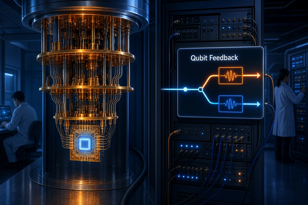
One measurement lets a controller choose the pulse settings that match the qubit’s current frequency mode.
A research team led by the University of Regensburg showed that a superconducting qubit can become substantially more reliable when its control system performs one extra measurement before a sequence of quantum operations. In the experiment, that measurement identified which of two possible resonance frequencies the qubit was using, allowing a real-time controller to adjust the microwave control frame; the average gate error fell from about 0.14% to 0.065%, a reduction of roughly 54%.
The result matters because it addresses a practical hardware problem rather than changing the quantum algorithm: small material defects can make a qubit’s frequency jump between known values, so a pulse calibrated for one frequency is slightly wrong for the other. The team describes the experiment in “Operating a bistable qubit” in Applied Physics Reviews, published on October 30, 2026, alongside the University of Regensburg’s November 3, 2026 announcement.
Key takeaways
- The experiment used a superconducting transmon qubit that switched stochastically between two resonance-frequency modes separated by approximately 374 kHz.
- A single-shot measurement supplied one bit of information about the active mode before subsequent quantum operations began.
- An FPGA-based controller updated the qubit’s control frame in real time, stabilizing gate performance over time.
- The reported average gate error decreased from approximately 0.14% without feedback to approximately 0.065% with feedback.
- This is error mitigation and adaptive calibration for one known hardware instability, not a replacement for quantum error correction.
What did the researchers announce?
Fabrizio Berritta, Ferdinand Kuemmeth, and collaborators demonstrated a feedback protocol for a bistable qubit: a qubit whose resonance frequency can switch between two discrete, known values. Their protocol uses one carefully timed measurement to infer the current frequency mode and then immediately selects the matching control frame for the operations that follow.
The work involved researchers from the University of Regensburg, Leiden University, and the Norwegian University of Science and Technology. The experiment ran on a superconducting circuit at the Israeli Quantum Computing Center, using a Quantum Machines OPX1000 controller with field-programmable gate array, or FPGA, processing for low-latency feedback.
The headline result is specific. With the feedback disabled, the researchers measured an average gate error of approximately 0.14%. With feedback enabled, they measured approximately 0.065%. That is about a 54% decrease in average error, while the improvement compared with the largest error observed without feedback reached 77%.
What is a superconducting qubit and why does its frequency matter?
A qubit is the physical unit of quantum information. Unlike a classical bit, which is represented as either 0 or 1, a qubit can be prepared in a quantum state that combines its two computational basis states. Quantum programs manipulate those states with tightly controlled operations called gates.
In this experiment, the qubit was a superconducting transmon: a tiny electrical circuit fabricated on a chip and operated at temperatures below 10 millikelvin. It was controlled with microwave signals. The frequency, phase, duration, and amplitude of those signals must match the qubit accurately enough to produce the intended rotation of its quantum state.
Resonance frequency is the frequency at which the qubit responds to control signals. A helpful beginner analogy is a musical instrument: if the instrument moves out of tune, a performer can make the same physical motion but produce a different note. Similarly, a microwave pulse calibrated for one qubit frequency can cause a small but meaningful control error if the qubit has moved to another frequency.
The two frequencies in this study were not the qubit’s computational values 0 and 1. They were two physical operating modes of the same device. In the high-frequency mode, the qubit frequency was approximately 5.10 GHz; in the low-frequency mode, it was lower by approximately 374 kHz. The qubit could support quantum computation in either mode, but the controller had to know which mode was active in order to apply the right pulse settings.
Why do qubits switch between two frequencies?
The study attributes the bistability to likely coupling between the qubit and a slow microscopic two-level-system defect, usually shortened to TLS. These defects can occur in materials and interfaces used in solid-state quantum hardware. Prior NIST research has also reported that a small number of microscopic fluctuators can correlate with changes in a transmon qubit’s coherence properties and transition frequency.
Such a defect can change configuration unpredictably. When that happens, it changes the qubit’s frequency by a discrete amount. This behavior is often called telegraphic noise because the device appears to switch between distinct settings instead of drifting smoothly through every possible value.
That distinction is important. Conventional recalibration can handle gradual drift when there is time to run characterization experiments, analyze the results, and update parameters. A qubit that can jump between two settings during an experiment needs a much faster response. The control system must detect the state of the hardware and adapt before the next gate sequence suffers from the mismatch.
How does the one-bit feedback protocol work?
The researchers call their approach 1-bit feedback. The name reflects the amount of information needed for this case: there are two possible frequency modes, so one binary measurement result is enough to select between them.
The protocol starts with a short diagnostic sequence, sometimes called a syndrome cycle in the paper. It is separate from the computation the researchers want to run. The controller prepares the qubit, lets it evolve for an optimized waiting time, and then measures it. Because the two resonance frequencies cause different phase evolution during that wait, the measurement outcome reveals which mode is likely active.
- The controller initializes the qubit in a known state.
- A microwave pulse places the qubit into a superposition suitable for frequency discrimination.
- The qubit evolves for a selected interval, during which the two possible frequency modes accumulate different phases.
- A second pulse maps that phase difference onto a measurable result.
- A single-shot measurement returns a binary outcome that identifies the current mode.
- The controller updates the microwave control frame and runs the following quantum operations using parameters matched to that mode.
In simple terms, the measurement does not repair the material defect. Instead, it tells the controller which version of the qubit it currently has. The controller then compensates for that condition in real time.
What does “control frame” mean in this experiment?
Quantum control software often describes a qubit relative to a rotating reference frame. That reference frame tracks the expected phase evolution of the qubit while microwave pulses apply rotations around chosen axes. If the assumed frequency is wrong, the frame gradually becomes misaligned with the physical qubit.
The effect is especially harmful for superposition states. In the wrong frame, the state accumulates an unwanted phase. Repeated operations then produce results that deviate from the intended circuit, increasing gate infidelity.
The feedback loop updates the controller’s frequency reference after the diagnostic measurement. It therefore changes the interpretation and timing of later control pulses to match the detected mode. The paper reports that this suppresses the Ramsey beating caused by averaging the two modes and eliminates the large time-dependent fluctuation in measured gate errors.
How did the experiment reduce the error rate?
The experiment compared qubit operations with and without the adaptive feedback step. Without feedback, the controller did not know whether the qubit was in the high- or low-frequency mode. As the device switched modes, gate quality varied over time because the control pulses were periodically calibrated for the wrong frequency.
With feedback, the controller performed the extra single-shot measurement, inferred the mode, and selected the corresponding control frame. The study reported an estimation bandwidth of approximately 136 kHz. That bandwidth had to be fast relative to the switching process so the information remained useful when the following gate operations began.
| Condition | What the controller knows | Reported result |
|---|---|---|
| Without feedback | The controller uses one fixed frame despite frequency switching. | Average gate error of approximately 0.14%, with substantial variation over time. |
| With 1-bit feedback | A single-shot result identifies the active frequency mode before the gate sequence. | Average gate error of approximately 0.065%, about 54% lower. |
| Worst observed no-feedback case versus feedback | The comparison includes the largest observed error when the qubit was not adjusted. | Error reduction reached 77%. |
This result should be read carefully. It is an experimental result for one superconducting qubit with two known frequency modes and a specific control setup. It does not mean that any qubit error can be halved by adding a measurement, and it does not establish a universal error rate for superconducting processors.
How is this different from quantum error correction?
Quantum error correction protects logical quantum information by encoding it across multiple physical qubits and repeatedly measuring error syndromes. It is a central long-term requirement for fault-tolerant quantum computing, but it needs substantial hardware resources and high-quality physical operations.
The 1-bit feedback experiment is a lower-level hardware-control technique. It identifies a known physical instability in one qubit and adjusts the pulses before executing operations. It does not encode a logical qubit, correct arbitrary quantum errors, or eliminate the need for quantum error correction.
However, the approaches can be complementary. Better physical gate fidelity gives error-correction schemes better inputs. The paper also notes that temporal correlations caused by individual defects can be relevant for ancilla qubits used in syndrome extraction, where independent noise assumptions are important.
What are the limits of this approach?
The method depends on several conditions. First, the possible qubit frequencies must be known in advance. A controller cannot choose the right calibration from two options if it has not identified those options during characterization.
Second, the modes must be sufficiently separated for a short experiment to distinguish them reliably. In this case, the approximately 374 kHz frequency difference created enough measurable phase separation during the diagnostic interval.
Third, the hardware condition must remain stable long enough for the measurement and controller update to matter. If the qubit changes modes faster than the system can estimate and react, a single result can already be obsolete when the next control pulse arrives.
There is also an overhead trade-off. The added measurement takes time and can disturb the qubit state, which is why the protocol is used before the operations being stabilized and why its sequence is designed around the control task. The value of feedback depends on whether the gain in fidelity exceeds the cost of the diagnostic step for a particular workload and device.
How can beginners get started with real-time quantum control?
Beginners do not need a dilution refrigerator or an FPGA controller to understand the central engineering pattern. The pattern is: characterize a noisy device, measure a state that predicts an error, then use a classical controller to select better quantum-control parameters before executing the next operation.
At the conceptual level, start by learning how a Ramsey experiment exposes a frequency mismatch. A qubit is prepared in a superposition, allowed to evolve, and measured after a controlled delay. When the assumed and actual frequencies disagree, the observed phase changes. In the Regensburg experiment, that same physical sensitivity becomes useful information for mode classification.
At the hardware level, real-time feedback requires measurement, classical processing, and pulse generation to work within a tight timing budget. The OPX1000 documentation describes support for passing measurement outcomes into feedback logic and for changing control flow or parameters during an experiment. The research result shows why that classical control path is increasingly part of the quantum-computing stack rather than merely laboratory infrastructure.
The practical lesson is not that software can make imperfect quantum hardware perfect. It is that adaptive control can prevent a known, measurable device fluctuation from becoming an avoidable gate error. As superconducting systems scale, automated calibration and feedback may help operators preserve performance even when a small number of defects remain.
Frequently asked questions
Did the measurement change the qubit from 0 to 1?
No. The additional measurement was used to determine which physical resonance-frequency mode the qubit occupied. Those modes are not the qubit’s computational 0 and 1 states; they are two possible operating conditions of the device.
What error reduction did the experiment report?
The researchers reported that the average gate error fell from approximately 0.14% without feedback to approximately 0.065% with feedback, a reduction of about 54%. They also reported a 77% reduction relative to the largest error observed without feedback.
What caused the qubit’s frequency to switch?
The paper describes the switching as likely caused by coupling to a slow microscopic two-level-system defect. Such defects can produce discrete, telegraphic changes in the qubit’s operating frequency.
Is 1-bit feedback quantum error correction?
No. It is a real-time calibration and error-mitigation method for a specific, known hardware instability. Quantum error correction uses multiple physical qubits to protect logical quantum information against a broader set of errors.
When does this feedback method work?
It works when the possible frequency modes are known and sufficiently distinguishable, and when each mode remains stable long enough for a measurement result to drive a useful update to the control signals.
Based on reporting by uni-regensburg.de, Applied Physics Reviews, Phys.org, National Institute of Standards and Technology and Quantum Machines Documentation.
Join the conversation! Your thoughts help the community grow.